 The Smart
Global Optimization Technology
The Smart
Global Optimization Technology
SmartDO eNews Feb. 14, 2008
: Crashworthiness Optimization
Until today, crashworthiness optimization is still considered
a state-of-the-art. Either in the industrial application or academic
research field, there are not many successful and practical example available
today. There are few common difficulties of crashworthiness optimization
from the aspect of practical application, as listed below
(1) Due to the nature
of the problem, crashworthiness simulation is usually dynamic and nonlinear.
Which means the computational time is much more expensive than regular
numerical analysis.
(2) In real life, the industries
usually use explicit dynamic finite element analysis techniques. Serious
numerical noise has been observed in such application.
(3) The numerical scheme mentioned above is sensitive to mesh
quality and pattern too. Which means a parametric model with free mesh
may or may not be proper for the purpose of design sensitivity study.
(4) Parametric modeling
is also an issue. How to create a seamless parametric model and combine
with pre-processor, post-processor and the solver for numerical optimization
is constantly a interested subject of research.
With the powerful solver in SmartDO, all these issues can be resolved
easily. In this issue of SmartDO
eNews, we will show you one example of crashworthiness optimization using
SmartDO.
Problem Description
A crash box as shown in Figure 1 is often attached to the front
bumper of the vehicle, and used for absorbing energy and inducing deceleration's.
The box needs to absorb the impact energy of a rigid wall with 100 kg
of mass and 13.9 m/sec of velocity (also shown in Figure 1). The reaction
force should be as small as possible, and there is also limitation on how
much the box can deform. Finally, the profile of the box needs to be inside
certain envelop.
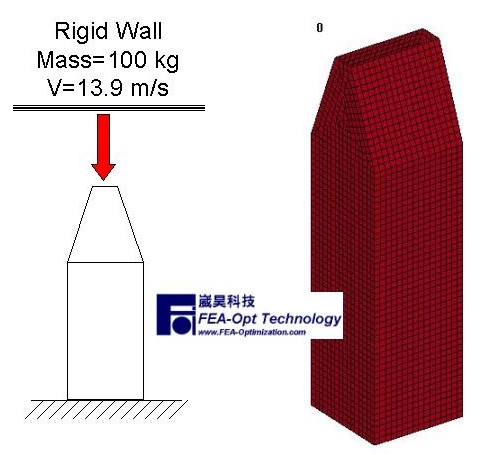
Figure 1 Configuration
of a Typical Crash Box
Figure 2 shows the Deformation VS Reaction Force
of the crash box
under impact loading. Figure 3 shows the deformation of the box simulated
by LS-DYNA. We will now use SmartDO to optimize the design.
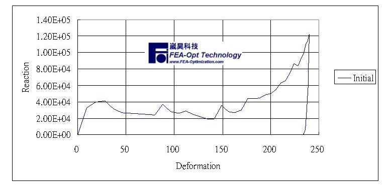
Figure 2 Deformation VS Reaction Force of a Typical Crash Box
Under Impact Loading
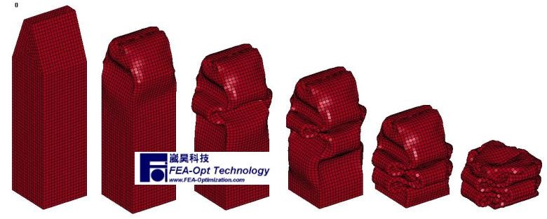
Figure 3 Crash Deformation
of a Typical Crash Box Simulated by LS-DYNA
Software
The following software will be used for this problem.
(1) LS-PrePost 2.3 for pre- and post-processing (http://www2.lstc.com/lsprepost.htm) .
(2) LS-DYNA for explicit transient finite element analysis (http://www.lstc.com)
(3) SmartDO for system integration and design optimization (http://www.fea-optimization.com/SmartDO/index_e.htm )
Modeling Details and Problem
Formulation
In order to solve this problem by Numerical Design Optimization,
we will have to "formulate" the problem such that it can be fit into
the solution mechanism of design optimization software, such as SmartDO.
Here we will model and formulate this problem as follows
Units and Material Properties
The units used in the problem is mm-g-msec. The material used
for the crash box is Aluminum EN AW 1200 O UNI EN 573-3, with the following
parameters
- Young's Modulus = 70000
MPa
- Tensile Yield
Stress = 82 MPa
- Poisson's Ratio
= 0.33
- Density = 2.71E-3
g/mm^3
- Tangent Modulus
= 2000 MPa
The material formulation
is assumed to be piecewise-linear plasticity. Material failure/rupture
is not considered here. The thickness of the box is 2 mm.
Parametric Modeling
The crush box is decided by 6 (shaping) parameters, namely X(1)
to X(6) as shown in Figure 4. This model was built in LS-PrePost 2.3,
including its geometry, mesh and all the LS-DYNA input keywords. Currently
it is not very straightforward to build the shaping
parametric model with LS-PrePost. However with the Pre-Processor for Embedded
Tcl/Tk (PET) in SmartDO, the users can actually apply Tcl/Tk on the input
batch file of LS-PrePost 2.3 (even if if doesn't support Tcl/Tk at all
!). Therefore with careful arrangement, a usual input batch modeling file
in LS-PrePost can be easily transferred into a parametric model with SmartDO.
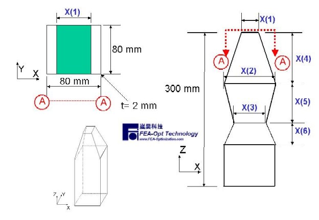
Figure 4 Parametric Model of the Crush Box
Design Optimization Formulation
As mentioned above, there are three major tasks in optimizing
a crush box : maximum reaction force, energy absorption and maximum
deformation. They are formulated as
- Find : X(1)~X(6)
- To Minimized : maximum
reaction force of the tube
- Subjected to :
- Energy Absorption >
9.156 E6
- Maximum Deformation <
241 mm
- With
- 20 < X(1) < 80
- 20 < X(2) < 80
- 20 < X(3) < 80
- 10 < X(4) < 80
- 10 < X(5) < 80
- 10 < X(6) < 80
- Initial Design
- X = < 20, 80, 80,
75, 80, 80 >
Note that, here the constraints
of energy absorption and maximum deformation are taken from the initial design.
That is, we want SmartDO to improve the design as much
as we can based on the initial
configuration.
Design
Optimization
SmartDO successfully
optimizes the problem without much difficulty. The details are explained
below.
Final Result
SmartDO comes up with
the final configuration with the design variables of
- X = < 20, 68, 68,
80, 10, 80 > (the initial design is X = < 20, 80, 80, 75, 80, 80
> )
Figure 5 shows the
configuration of the Initial Design (Left) and the Optimal Design (Right).
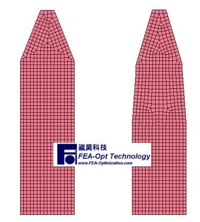
Figure 5 Configuration of the Initial Design (Left) and the Optimal
Design (Right) by SmartDO
As we can see in Figure 6, SmartDO tries to lower the peak force
yet still providing the same energy absorption, by re-arranging the reaction
curve. Actually in some publication, the initial design was already considered
optimal, but SmartDO can still reduce about 20% of its peak reaction force.
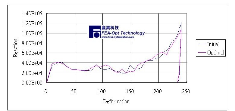
Figure 6 Deformation VS Reaction Force for Both Initial Design and
the Optimal Design by SmartDO
Figure 7 shows the crushed deformation of the optimal design simulated
by LS-DYNA
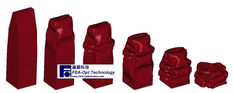
Figure 7 The Crushed Deformation of the Optimal Design Simulated
By LS-DYNA
Computational Expense
One interesting thing
to be observed would be the computational effort taken by SmartDO. As
mentioned before, crashworthiness simulation is usually very time-consuming.
Therefore if the optimization package needs too much finite element analysis,
the whole process will be very unpracticed.
For the example shown here, we have used the Robust Genetic Algorithms
(RGA) in SmartDO (see these publications
for reference). Since in the Genetic Algorithms we always have to discretize
the design variables, we have chosen 8 points (2^3) for each design variables.
If a DOE is to be used, it will requires the computations of 8^6=262144
sample points. For the current example, however, SmartDO has only taken
63 finite element analysis to achieve the optimal design shown here.
Conclusion
and Remarks
In this issue of the
SmartDO eNews, we have shown you how we can perform crashworthiness optimization
with SmartDO. One thing important is that, the computational effort taken
by SmartDO is very inexpensive. It is obvious that, SmartDO is a practical
tools for industrial crashworthiness optimization.
For details about SmartDO, please visit our web site at http://www.fea-optimization.com/SmartDO/index_e.htm.
|
|
|
|
|
|
All brand or product names are trademarks
or registered trademarks of their
respective holders. Copyright of all materials
in the links belongs to their respective authors.
I am not responsible for any contents inside any links.
(c)Copyright, 1998-, Shen-Yeh
Chen, Ph.D. All rights reserved.
|
|
